What is a Nipkow disk?
A Nipkow disk, or scanner disk, is the invention of Paul Gottlieb Nipkow, an electrical engineer from Germany. This disk later became the main component of electromechanical television. The first appearance of electromechanical televisions was in the 1920s and 1930s.

Paul Gottlieb Nipkow
Paul Gottlieb Nipkow was a technician and inventor from Germany. He lived from 1860 to 1940.
His most famous invention was a snail-shaped disk used to divide a picture into lines and dots arranged next to each other. This disk later became the main component of mechanical television.

Electromechanical Televisions
A scan disk consists of holes positioned at different distances and angles from the center of the circle. As it rotates, it covers an area that can be used to display pictures. This disk was the fundamental component of mechanical TVs.

Personal Inspiration
Besides the beautiful history of displays, creating an electromechanical television provided many learning opportunities for me. From designing the disk using mathematical formulas to building the project’s body, creating an LED driver with a frequency of 9000 hertz, and tuning the picture, each step offered new learning experiences.
The purpose of building this project
The functionality of displays has always inspired me, and I have always been fascinated by how electromechanical TVs and CRT displays work. I have learned a lot from them, especially about the evolution of displays. In the past, technology was not as advanced, and displays were neither as fast nor as easy to use or create. This is why they can still teach us a thing or two.
The Limitations of the Nipkow Display
This old technology, which created images, also had limitations!
To display a bigger picture, a larger disk was required. Another limitation was the speed, which had to remain stable to produce a clear image. For higher resolutions, more holes were needed in the disk. Despite these challenges, it was still possible to display images on them.

Part One: Mechanical Design and Manufacturing
Disk Structure
Before we start designing the disk using Fusion 360, we need to determine the distance of each hole from the center and its angle relative to the previous hole.

In the picture above, you can see a snail-like pattern. Each hole is responsible for displaying a column (this disk has 15 holes, meaning it can display 15 columns). The design ensures that after the current hole passes the designated area (the display rectangle), the next hole enters the area, starting the next column.


This special design allows us to have a rectangular display. You can use this website to explore different Nipkow disks with various sizes and hole arrangements.
This weblog provides more information on designing a Nipkow disk. However, for simplicity, we will use the Python programming language to write a program that calculates the distance of each hole from the center and the angle of each hole.
The code below is used to calculate the position of each hole in the Nipkow disk. First, we set the variables, such as the diameter of the disk (20mm), the window size (30mm x 47mm), the pitch, and the offset. Then, we calculate the total number of holes based on the width and height of the window we have already set. After that, we use a for loop to calculate the distance from the center and the angle from the previous hole for each hole, and then print the result with a precision of 0.01 for the float values.
import math

disk_size:float = 200        # diameter of the circle (200mm - 20cm)
rectangle_height:float = 30  # Height of the window (30mm)
rectangle_width:float = 47   # Width of the window (47mm)
padding:float = 2            # Offset of the first hole
pitch:float = 3.26           # Pitch of the holes

# Calculate the total number of holes
total_holes:int = int(abs(rectangle_width / pitch)) + 1

# Calculate each angle and distance
for i in range(total_holes):

	# Calculate the distance from the center of the current hole
	distance:float = (disk_size/2) - (padding) - (i * pitch)

	# Calculate the angle of the current hole
	angle:float = 2 * math.asin(rectangle_height / (2 * distance)) * (180 / math.pi)

	# Print the angle and distance with an accuracy of 0.01 float
	print(f"Angle: {angle:.2f},\tDistance: {distance:.2f}")
Now, if we run the program with a diameter of 20cm and a window size of 47 by 30 millimeters, we get the following result:
Angle: 17.61,   Distance: 98.00
Angle: 18.22,   Distance: 94.74
Angle: 18.87,   Distance: 91.48
Angle: 19.58,   Distance: 88.22
Angle: 20.34,   Distance: 84.96
Angle: 21.16,   Distance: 81.70
Angle: 22.05,   Distance: 78.44
Angle: 23.02,   Distance: 75.18
Angle: 24.08,   Distance: 71.92
Angle: 25.24,   Distance: 68.66
Angle: 26.52,   Distance: 65.40
Angle: 27.94,   Distance: 62.14
Angle: 29.52,   Distance: 58.88
Angle: 31.29,   Distance: 55.62
Angle: 33.29,   Distance: 52.36
For example, the first line tells us that the angle of the first hole is 17.61, and the distance of the hole from the center is 98mm. Similarly, the second line shows the angle of 18.22 from the previous hole, and so on.
Now that we know where to place each hole, it’s time to design the disk.
Designing the Disk Using Fusion 360
In the first step, we create the sketch of the disk using the information we just calculated, as shown in the following picture.

The diameter of each hole in this design is 2.4mm, and there are two holes in the center for the motor attachment.
For the holes with angles of 34.6 degrees and 31.3 degrees (the last hole), there is a small interrupter. This interrupter will help us calculate the Revolutions Per Minute (RPM) of the motor and determine the timing for displaying the exact color, which we will discuss later in the post.
In the second step, we extrude the sketch to create a 3D design.

To reduce the weight of the disk for 3D printing, the thickness of the disk is set to 1mm, while the motor attachment hole and the interrupter have thicker extrusions.
Designing the Body of the Display
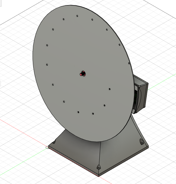
For simplicity, we create the body of the project using a 3D printer. However, 3D printing is not the best choice—laser-cut CNC machines offer greater accuracy. For example, a disk made with laser cutting and aluminum is cleaner than one made with 3D printing. Aluminum is also a good choice because it is lightweight. On the other hand, 3D printing is cheaper. There are other options, such as wood, but keep in mind that the material should NOT allow light to pass through, as this would ruin the picture.
Creating a Nipkow display is possible with various materials. Since we designed our body in Fusion 360, we are going to create the project using a 3D printer.
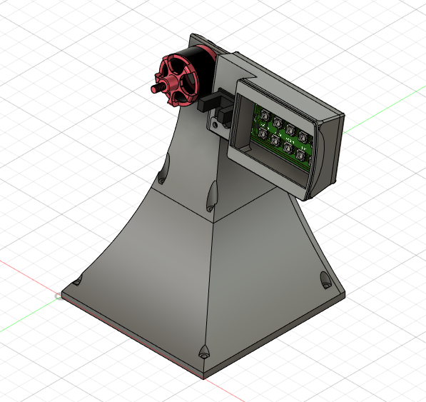
The body of this display, aside from the disk, is made up of five parts. The first part is called the BOTTOM, which serves as the place for housing electronic circuits.

The second part is called the FRONT. This part covers the electronic circuits inside and is connected to the Bottom part with four screws.

The third part, called the TOP, connects to the FRONT with four screws and is designed to hold the motor, LED, and photo interrupter speed sensor. This part has a slight curvature to hold the disk, providing a better viewing angle. Additionally, its design allows all the wires from the motor, LED, and sensor to pass through and reach the electronic circuit inside the body.

The fourth part, called the CONNECTOR, attaches to the TOP and holds the motor in place. This body features a rail design that helps adjust the position of the LED and speed sensor.

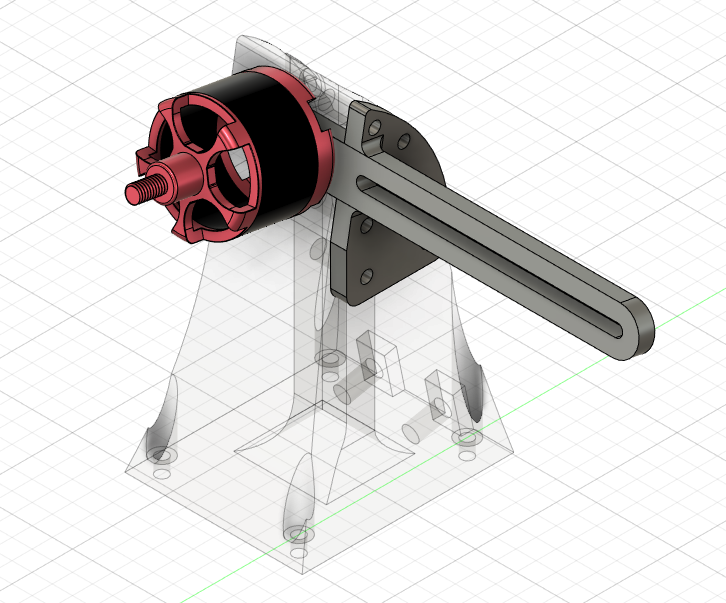
The fifth and final part is an enclosure that holds the LED and speed sensor in place. It attaches to the rail with two screws.

The Overview of the Design:
Second Part: Electronics and Control
We need a microcontroller to display the pictures, but which one is the best?
To display the pictures, we need a high-frequency microcontroller. For example, the LED should operate at a frequency of 9000 hertz, and the microcontroller must calculate the rotation of the disk (RPM of the motor). It also needs to trigger an interrupt when the interrupter passes by. Additionally, the microcontroller must receive images and display them.
Now that we know what we need from our microcontroller, we should choose one that meets these requirements while remaining cost-effective. For example, since we don’t need more than 100 MHz, we can opt for a cheaper option.
STM32 microcontrollers are a good choice—they are affordable and offer a suitable frequency for our needs. One such option is the STM32F103, which provides a 72 MHz frequency for this project. It also has three UARTs that can be used to receive images and four timers that help with microsecond delays and Timer Capture for calculating the motor’s RPM.
One of the most well-known boards that use this microcontroller is the “BLUE PILL.” This board makes working with the STM32 easier and provides all the features we need.

The microcontroller is also responsible for starting the motor. For this project, we use a brushless motor, which has a relatively high speed and is commonly used in drones. In this display, we need a motor with a minimum speed of 1500 revolutions per minute (RPM).

To start a brushless motor, we need a component called a “speed controller.” This component helps us start the motor and allows us to adjust its speed according to our needs.

Creating a Custom RGB LED
To display colorful images, we need an LED with adjustable colors. These LEDs are known as RGB LEDs. Additionally, the RGB LED must cover the window in our disk. One type of LED that meets this requirement is the “NeoPixel.” These LEDs are addressable, which means we can change their color through our program.
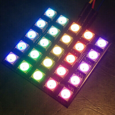
In the module above, we need 25 LEDs, and we can change their color to anything we want. However, we don’t need a different color for each LED—all LEDs should have the same color (acting like a single large LED).
This is why NeoPixel is not the best choice. The time required to set the color for each LED is 30 microseconds, and since we have 25 LEDs, the total time needed is 750 microseconds, which is too much. We have a maximum of 100 microseconds to set the LED color.
The next option is to build a series LED matrix where all LEDs share the same color with a single addressing. For this, we need an addressing chip called WS2811, which is made by the same company that created NeoPixel, Adafruit.
The functionality of this chip and its addressing method are similar to NeoPixel, and it provides a constant current of 18.5 mA, which we can use with 5050 RGB LEDs. These LEDs have the same shape as WS2812 (used in NeoPixel), but they are not the same—these LEDs are not addressable and function like regular LEDs.
By using the WS2811 chip, we can create a series of 15 LEDs (which is enough to cover the 30mm × 47mm window) and control all of them by addressing only the chip. This way, we can change the LED color about 25 times faster.
The schematic of the circuit is as follows:

Its 3D PCB shape is as follows:

This circuit, with 13.5V, provides good lighting, and by using a 5V regulator, it supplies power to the WS2811 chip.
By using this PCB, we can control all of the LEDs at once with a timing of 30 microseconds + 50 microseconds for the reset time (80 microseconds in total). The reset time prevents the IC from acting like the NeoPixel and setting the addressing to the next IC. By waiting for 50 microseconds (according to the datasheet) and addressing it again, the same IC color is set.
But there is a problem: some of the ICs, like the one I had, are not original and are fake. They work properly, but not as specified in the datasheet. The issue I encountered is that the reset time was 200 microseconds instead of 50 microseconds, which is too long for setting the color of the LEDs.
LED Driver Design with Transistor
For fast turning on and off of the LEDs, we need a constant current driver that can be used in the matrix we created. This allows us to control three colors—Red, Green, and Blue—and by mixing them, we can have only 8 colors, which is known as the EBU colors.
As mentioned before, the WS2811 always provides a current of 18.5mA, which is suitable for 5050 RGB LEDs. Here, we need a constant current LED driver that delivers a constant current of 18.5mA.
In this circuit, we use 2 NPN transistors and 2 resistors for 15 LEDs. The transistors we are using are 2N2222, which meet our needs.
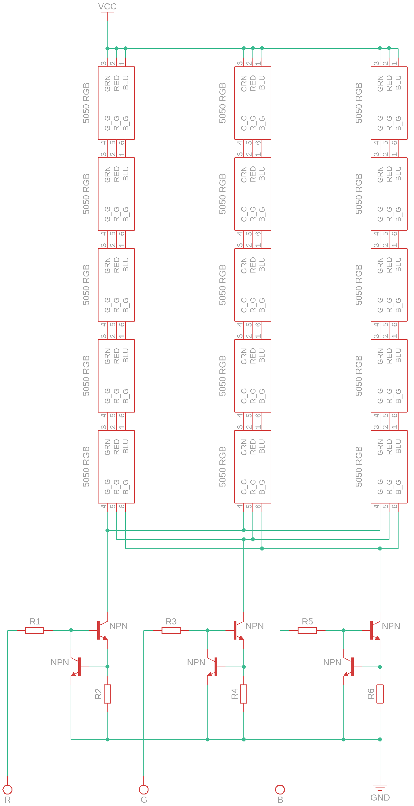
In this circuit, the resistors R1, R3, and R5 have the same value, as do R2, R4, and R6. The value of these resistors is important to ensure we get the 18.5mA current.
The value of the second group (R2, R4, and R6) is 33 ohms, given a voltage of 0.6V and a current of 18.5mA. The value of the first group (R1, R3, and R5) is 8.75 ohms. This value is obtained based on the transistor’s beta value (equal to 75) and a voltage of 2.1 volts.
Microcontroller Programming
This project is written in the C programming language. The reason it is written in C is its performance—the code runs faster. As I explained, in this project, we need to execute our code as quickly as possible to meet our needs and display a clear image.
Additionally, C is used in most embedded projects and provides access to a good number of libraries that can help us.
Now that we have created our LED driver, we need to control it. Most importantly, we must calculate how long each LED should be ON or OFF.
And we have already calculated the angle of each hole. Each hole is responsible for one column, but each column does not have a fixed color and is divided into 16 rows. This means that the LED, for each turn between two holes, changes its color 16 times.
Before we calculate how long each LED should be on (and what color to display), we need to determine the motor’s RPM. This is done using timers. We set a timer to count, and by using the signal from the sensor when the timer overflows, we calculate the RPM and update the rpm variable.
static const int ticks = 13;  // 13 us
static int rpm = 0;


void timerCallback(timeHandle_t htim){
    if(timer.capture.ccr < 0){ return; }
    rpm = 60 * (1 / ((timer.capture.ccr * ticks) * 0.000001));
    ...
}
The above code updates the value of the rpm variable using the timer’s counting time (which is 13 microseconds) through timer capture. If the timer counter value is negative (indicating timing after the timer’s overflow), we skip the rest of the calculation.
Now that we have the RPM, we can use it to calculate the timing of the LEDs for each hole and store the values in an array. Additionally, we can determine the time it takes for the first hole (outer hole) to reach the correct position.
// Precomputed constants
#define SECONDS_PER_MINUTE 60
#define DEGREES_PER_REVOLUTION 360
#define NS_TO_US 1000
#define ARRAY_SIZE 15
#define BASE_SCALE_FACTOR_NS (1000000000 / (16 * 360))                    // Precomputed base scale factor in ns/RPM
#define RPM_TO_DEG_PER_SEC (DEGREES_PER_REVOLUTION / SECONDS_PER_MINUTE)  // 6 degrees/sec per RPM


// Precomputed base timing points in nanoseconds (const to prevent modification)
static const int baseTimingPoints[ARRAY_SIZE] = {
    17610, 18210, 18870, 19570, 20330,
    21150, 22040, 23000, 24070, 25230,
    26500, 27930, 29510, 31300, 33290
};


// Global variables
static int timingArray[ARRAY_SIZE] = {0};    // Calculated timing values in µs
static int interruptFlag = 0;                // Interrupt status flag
static int timingAdjustmentDelay = 0;        // Adjustment delay in µs


// Precomputed constants for adjustment points
static const int BASE_POINT_A_NS = 34600;   // Primary timing reference in ns
static const int BASE_POINT_B_NS = 17600;   // Secondary timing reference in ns


void timerCallback(timeHandle_t htim) {
    ...
    // Convert RPM to degrees per second using precomputed factor
    int totalDegreesPerSecond = rpm * RPM_TO_DEG_PER_SEC;

    // Calculate scaling factor once per call
    int timeScale = BASE_SCALE_FACTOR_NS / totalDegreesPerSecond;


    // Update timing array with scaled values converted to µs
    for (int i = 0; i < ARRAY_SIZE; i++) {
        timingArray[i] = (baseTimingPoints[i] * timeScale) / NS_TO_US;
    }


    // Calculate adjustment points directly in µs using precomputed base values
    int pointA = (BASE_POINT_A_NS * timeScale) / NS_TO_US;
    int pointB = (BASE_POINT_B_NS * timeScale) / NS_TO_US;

    // Compute final adjustment delay
    timingAdjustmentDelay = pointA - (pointB / 2);
    interruptFlag = 1;
}
Now, using the calculated RPM, we update the array. The value of each item, which corresponds to a separate hole, is divided by 16 because we have 16 rows.
At the end, we calculate the timing for the first hole (outer hole) to reach the correct position. Remember that there is a gap between the interrupter of the disk and the first hole. Also, note that the speed sensor is located in the middle of the LED enclosure.
The “interrupt Flag” variable is used to specify when to start displaying images. When the disk’s interrupter passes by the speed sensor (timer capture callback), this variable is set.
Finally, using the values we calculated, the program’s main loop begins displaying the image.
But first, to make the task easier, we create a function to help us set the color of the LEDs.
typedef struct {
    gpio_t red;
    gpio_t green;
    gpio_t blue;
} octaDisplay_t;


static octaDisplay_t display;


void setColor(int red, int green, int blue){
    gpinSet(&display.red, red ? PIN_ON : PIN_OFF);
    gpinSet(&display.green, green ? PIN_ON : PIN_OFF);
    gpinSet(&display.blue, blue ? PIN_ON : PIN_OFF);
}
Now, by using the “setColor” function, we can set 8 different colors: black, white, yellow, cyan, green, magenta, red, and blue.
Now that we have written the function for setting the colors, it’s time to implement the main loop of the program:
static int cntr = 0;          // Index of the current frame
static int frameCounter = 0;  // Number of times the same frame is displayed


// Display buffer containing preloaded frames
static const unsigned char buffer[50][672] = {
    ...
};


// Buffer for the current frame
static unsigned char displayBuffer[MAX_BUF_SIZE] = { 0 };


int main(void) {


    ...


    // Initialize timer capture for RPM measurement
    timerCaptureInit(&timer, B5_TIM3_CH2, CAPTURE_FALLING, ticks, timerCallback);


    int j = 0;


    while (1) {
        // Wait until the interrupt flag is set
        while (interruptFlag == 0) { __asm__ volatile ("nop"); }


        // Wait for the correct timing to align with the first hole
        delayUs(adjustDelay);


        // Track frame display count
        if (frameCounter == 10) {
            cntr++;
            frameCounter = 0;
        }
        frameCounter++;


        // Reset frame index if it reaches the last frame
        if (cntr == (sizeof(buffer) / sizeof(buffer[0])) - 1) { cntr = 0; }


        // Load the current frame into the display buffer
        memcpy(displayBuffer, buffer[cntr++], 672);


        j = 0;
        for (int i = 0; i < 14; i++) {
            int delayVal = array[i] - 12;
            for (int k = 0; k < 48; k += 3) {
                setColor(displayBuffer[j + k], displayBuffer[j + k + 1], displayBuffer[j + k + 2]);
                delayUs(delayVal);
            }


            // Turn off the LED (Black) after completing a column
            setColor(0, 0, 0);
            j += 48;
        }


        // Reset interrupt flag for the next cycle
        interruptFlag = 0;
    }


    return 0;
}
In the code above, the variable buffer holds the data for each frame. This array stores only 0 or 1, and its size is 672. This number is calculated based on the resolution of the display: 14 holes for each column (the last one, closest to the center, is not displayed due to the low frequency) and 16 rows. All of this is multiplied by 3 for each color—Red, Green, and Blue—and each number defines which color is supposed to be on.
static const unsigned char buffer[50][672] = {
    // R, G, B, R, ..., G, B
      {0, 0, 1, 1, ..., 0, 0},
    ...
};
After that, we load the current frame into the helper variable displayBuffer and set the color for the calculated duration. This should give us a clear image.
Preview and Conclusion
This display works in a way that at any given time, only one hole is within the display area. Each hole passes the same distance to create a rectangular picture. As the hole passes the designated area, the LED is responsible for changing color 16 times for each row. After that, the next hole appears in the area due to the way the disk is designed. This process happens 14 times to provide a clear rectangular picture.


Creating this display was incredibly satisfying and taught me a lot, from design challenges to hands-on making. It was one of the most fun projects I’ve done. One of the key challenges was implementing a 9000 Hz frequency for the LED, while another was tuning the display to produce a clear picture.
It’s interesting to know that old technologies still have something to teach us and that we can learn how they worked in the first place.
This project can still be improved, such as by adding UART to send images to it or creating a display that isn’t limited to 8 colors and can change at a higher frequency.
But in the end, we managed to create the high-frequency display, despite the color limitations, and adjusted and tuned the display to provide a clear picture.
Resources
At this link, you will find all the 3D models and code needed to create this project. By using these resources, you can create your own Nipkow display.